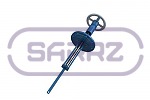
Tank clap valves
Description
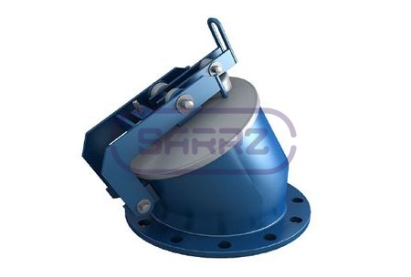
Tank clap valves completed with the actuator (control mechanism) MU (MUV) are installed on the inlet - distribution nozzle of vertical tanks for protection from petroleum products spill as a result of pipeline or shut-off valves damage while oil handling.
Their principle of action is to open the lid of the tank clap valve, which provides oil running. In case of emergency oil spill is excluded, as the functions of rapid closing and stopping the flow are provided. The equipment also prevents the reverse running of the operating product in the closed position.
The Saratov Reservoir Plant supplies own-produced tanks with the following types of equipment:
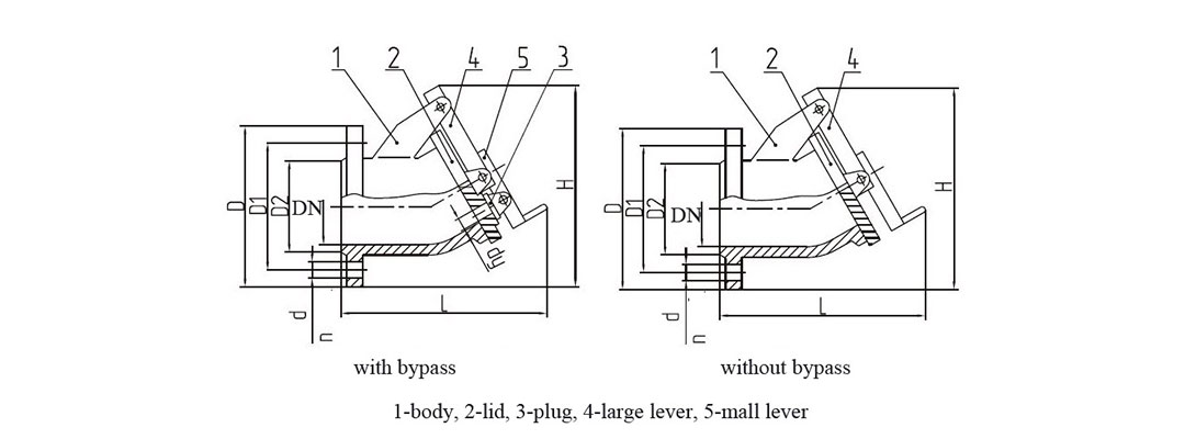
- tank clap valves without bypass DN80 and DN100
- tank clap valves with bypass DN150, DN200, DN250, DN300, DN400, DN500, DN 600, to simplify opening
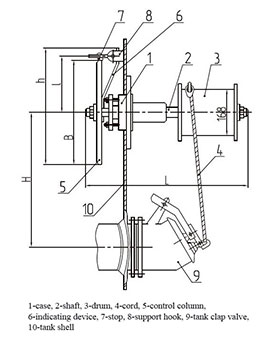
- side control mechanisms of tank clap valves MU
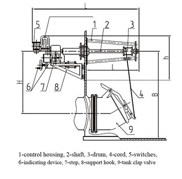
- upper control mechanisms of tank clap valves MUV
Tank clap valves XP: design and specifications
The design appears as a body with an oblique section and a lid with a lever located on it.
In order to avoid a friction sparks, the lid is made of aluminum intrinsically safe alloys for additional explosion and fire safety. The valves are mounted inside the tank on inlet - distribution nozzle. The opening is conducted with a cord, one end of which is fixed to the lever, and the second - to the control mechanism of the tank clap valve, which fixes the lid in the open position.
When filling the tank the lid is lifted automatically due to the product stream. Closure occurs at the steam stop. When emptying the lid is lifted by the control mechanism.
Technical specifications of Tank clap valves
| Criteria | XP–80 | XP-100 | XP–150 | XP–200 | XP–250 | XP–300 | XP–400 | XP–500 | XP–600 |
|---|---|---|---|---|---|---|---|---|---|
| without bypass | with bypass | ||||||||
| Diameter Nominal, DN | 80 | 100 | 150 | 200 | 250 | 300 | 400 | 500 | 600 |
| Pressure, MPa (kp/cm2) | 0.16 (1.6) | ||||||||
| Diameter Nominal, DN | - | - | 25 | 25 | 25 | 25 | 100 | 100 | 100 |
| Inside diameter of bypass hole dy, mm | 80 | 100 | 150 | 200 | 250 | 300 | 400 | 500 | 600 |
| Overall dimensions, mm, max: | |||||||||
| length L | 160 | 170 | 306 | 328 | 380 | 442 | 606 | 700 | 770 |
| width | 185 | 205 | 260 | 315 | 370 | 435 | 580 | 710 | 840 |
| height H | 212 | 281 | 308 | 370 | 385 | 504 | 686 | 840 | 960 |
| Connection size, mm: | |||||||||
| D | 185 | 215 | 260 | 315 | 370 | 435 | 580 | 710 | 840 |
| D1 | 150 | 170 | 225 | 280 | 335 | 395 | 525 | 650 | 770 |
| d | 18 | 18 | 18 | 18 | 18 | 22 | 30 | 33 | 36 |
| n, pcs | 4 | 4 | 8 | 8 | 12 | 12 | 16 | 20 | 20 |
| Weight, kg, max | 2.3 | 7 | 7.5 | 17.6 | 28 | 46.9 | 91.5 | 135 | 205 |
| Service lifetime, years, min | 15 | ||||||||
| Climatic category | N, NF placement category 1 as per GOST 15150.69 | ||||||||
Side control mechanisms of tank clap valves MU: design and specifications
They are necessary for opening and fixing the lid of the valve when emptying the tank. The housing itself is installed on the mount nozzle above the inlet - distribution nozzle inside the tank, and the driving gear is located outside.
The Plant SARRZ supplies the following modifications:
- MUI with hand gear DN80, DN100, DN150, DN200, DN250
- MUII with electrical drive DN300, DN400, DN600
Technical specifications of Side control mechanisms MU
| Criteria | MU–I | MU–II |
|---|---|---|
| Diameter Nominal DN, mm | 80–250 | 300, 400, 500, 600 |
| Length L, mm | 518 | 1676 |
| Height h, mm | 350 | 570 |
| Distance to the valve Н, mm | 900 | 1195 |
| Distance I, мм | 165 | 1020 |
| Distance to the tank bottom В, mm | - | 1695 |
| Weight, kg, max | 15 | 108 |
| Service lifetime, years, max | 15 | |
| Climatic category | N, NF placement category 1 as per GOST 15150.69 | |
Upper control mechanisms of tank clap valves MUV: design and specifications
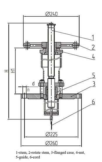
They are mounted either on the roof or on the neck of the tanks and are necessary to open the lid of the tank clap valve and fix it in the open position until the end of the draining operations.
We supply the following sizes:
- MUV-80 up to DN80
- MUV-250 up to DN250
- MUV-400 up to DN400
Technical specifications of Upper control mechanisms MUV
| Criteria | MUV–80 | MUV–250 | MUV–400 |
|---|---|---|---|
| Diameter Nominal DN, mm, max | 80 | 150; 250 | 400 |
| Overall dimensions, mm, max: | |||
| H | 990 | 1820 | 2120 |
| D | 260 | 260 | 260 |
| D1 | 225 | 225 | 225 |
| d | 18 | 18 | 18 |
| Number of holes n, pcs | 8 | 8 | 8 |
| Weight, kg, max | 17 | 25 | 30 |
| Pressure, MPa | 0,1 | ||
| Срок службы, лет, не более | 15 | ||
| Climatic category | N, T placement category 1 as per GOST 15150.69 | ||
How to buy Tank clap valves XP and actuator (control mechanism) MU (MUV) at the Saratov Reservoir Plant?
Our experts supply equipment as components of vertical tanks, and separately as well. In order to know the cost of Tank clap valves and actuator, You can:
- call at +7(8452)250-288
- send e - mail at with Diameter Nominal of the necessary equipment
- use the form "Request for quotation"
See also:
| Breather valves | Samplers | Tank hatches |
| Bottom cleanout boxes | Nozzles, nipples, connecting pipes, fittings | Flame arresters |
| Tank clap valves |
