Breather valves
   |
Description
Breather valves are an integral equipment of vertical tanks, which ensures explosionproof operation. In storage process of petroleum products or loading-unloading operations evaporation and vapor formation in the gas space occur. The pressure can also change within 24 hours due to enviromental temperature shift. Some operating processes are accompanied by air ingress from the outside. All these processes ("breathing") lead to pressure boost in the gas space, which can destroy the shell, force out the roof or lead to an explosion. To avoid this, breathing and safety valves are installed.
The purpose of breathing valves
In accordance with GOST 31385-2016 "Vertical cylindrical steel tanks for oil and petroleum products. General technical specifications" and STO-SA-03-002-2009 "Rules for design, manufacture and erection of vertical cylindrical steel tanks for oil and petroleum products" each tank must be equipped with a breathing valve.
Their main function is the regulation of pressure in the gas space or vacuum in vertical tanks.
In addition, they perform the following functions:
- maintaining of structural integrity
- reduction of atmospheric evaporation loss
- fire and explosion protection
- reduction in environmental pollution
- intrusion of dust, sand and other particles prevention
- prevention of upper and saturated lower layers mixing
Regulatory requirements for breather valves
- fixed operating value shall not exceed 20% of the tank pressure
- the throughput capacity should not be less than the capacity during loading-unloading operations with account of vapor formation during the oil migration, enviromental and gas space temperature shift
Types of breathing valves
Breathing valves are of two types:
- with mechanical shutter
- with hydraulic gate, which are used as safety valves
Design and function of breathing valves with mechanical shutter
Breathing valves with mechanical shutter are represented by several types:
- the breathing combination valve (KDS) with disk-reflector
- the combined mechanical breather valve SMDK
- the breathing enclosed valve KDZT
- the mechanical breathing valve KDM with internal flame arrestor
- the impermeable breathing mechanical valve NDKM
Mechanical breather valves differ in throughout capacity, set pressure and seating. Thus, SMDK can be installed on horizontal tanks, KDZT are used in vapor recovery systems of vertical tanks for flammable oil products, KDS and KDM are used with mainly with light oil products.
The principle of action is vapor surplus release or air supply from the atmosphere. Each valve has a normally closed shutter. At breathing (when evaporating) or filling loss the shutter plate is raised from the seat. The limit operating value is set at overpressure of the gas-air mixture or exceeding the vacuum.
Several requirements are applied to the breathing valves:
- the contact surfaces of the shutters, plates, fastening elements, seats must be impermeable, which is achieved due to their manufacture of materials that have low adhesive properties
- to avoid inner condensate storing the valve should have a minimum number of horizontal surfaces
- anticorrosive surface treatment is necessary, as the mass of plates may be reduced resulting from the corrosion
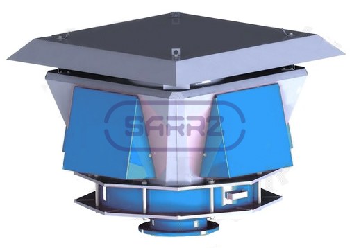
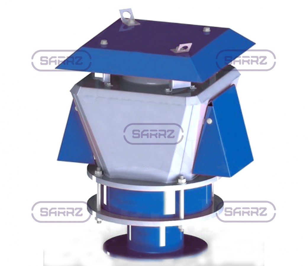
Technical description of the breathing combination valve (KDS)
The KDS valves are installed on vertical tanks to regulate pressure during loading-unloading operations and operating temperature changes. For more reliable operation, a disc-reflector and a fire safety device are provided.
The principle of operation is to open the shutter if the designed operating values are achieved and closing it when reduced. If necessary, it is possible to adjust it to the operating mode of the safety valve.
The specified service life of the KDS is 15 years, after which it is recommended to replace it with the possible changes in the volume of loading-unloading operations. They are manufactured in climatic categories N and NF, placement category 1. When operating in a cold climate, it is possible to install the automatic heating system, which provides the operating temperature of the fire safety device.
| KDS-1500 drawing | Criteria | KDS-1500/150 | KDS-1500/200 | KDS-1500/250 | KDS-1500/350 | KDS-1500/500 | |
|---|---|---|---|---|---|---|---|
 |
Diameter Nominal DN | 150 | 200 | 250 | 350 | 500 | |
| Pressure, Pa (mm w.g.) | 2000(200) | ||||||
| Vacuum, Pa (mm w.g.) | 250 (25) | ||||||
| Actuation pressure, Pa (mm w.g.) | 1500-1600 (150-160) | ||||||
| Actuation vacuum, Pa (mm w.g.) | 100-150 (10-15) | ||||||
| Throughput capacity, m3/h | 450 | 750 | 1000 | 1300 | 1500 | ||
| Area of seat passage, sm2 | 940 | ||||||
| Area of vacuum seat passage, sm2 | 4 × 475 = 1900 | ||||||
| Overall dimensions, mm, max: | |||||||
| -length | 900 | ||||||
| -width B | 900 | ||||||
| -height H | 800 | 900 | 900 | 900 | 800 | ||
| Connection sizes, mm | D | 260 | 315 | 370 | 485 | 640 | |
| D1 | 225 | 280 | 335 | 445 | 600 | ||
| d | 18 | 18 | 18 | 22 | 22 | ||
| n, pcs | 8 | 8 | 12 | 12 | 16 | ||
| Weight, kg, max | 85 | ||||||
| KDS-3000 drawing | Criteria | KDS-3000/250 | KDS-3000/350 | KDS-3000/500 | |
|---|---|---|---|---|---|
 |
Diameter Nominal DN | 250 | 350 | 500 | |
| Pressure, Pa (mm w.g.) | 2000 (200) | ||||
| Vacuum, Pa (mm w.g.) | 250(25) | ||||
| Actuation pressure, Pa (mm w.g.) | 1500-1600 (150-160) | ||||
| Actuation vacuum, Pa (mm w.g.) | 100-150 (10-15) | ||||
| Throughput capacity, m3/h | 1100 | 2400 | 3000 | ||
| Area of seat passage, sm2 | 1880 | ||||
| Area of vacuum seat passage, sm2 | 3760 | ||||
| Overall dimensions, mm, max: | |||||
| -length | 1300 | ||||
| -width B | 1300 | ||||
| -height H | 1100 | 1170 | 1060 | ||
| Connection sizes, mm | D | 370 | 485 | 640 | |
| D1 | 335 | 445 | 600 | ||
| d | 18 | 22 | 22 | ||
| n, pcs | 12 | 12 | 16 | ||
| Weight, kg, max | 140 | ||||
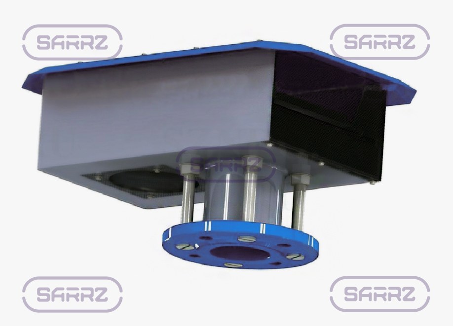
Technical description of the combination mechanical breathing valve SMDK
SMDK valves are used with vertical tanks to compensate pressure fluctuation during filling/unloading or emptying or changing of thermal operational mode. They should be installed strictly in accordance with the volume of inlet — distribution operations.
The design of the SMDK includes fire-stop assembly, which prevents the flame or nucleus of flame penetration. To prevent small particles and dust ingress on the surface of the liquid, a filtering mesh is provided. Mounting is flange through the tightening, which ensures interface integrity.
SMDK valves are manufactured in climatic categories N and NF, placement category 1.
The specified service life is 15 years, after which it is recommended to replace or test it.
| SMDK valve drawing | Criteria | SMDK-50АА | SMDK-100АА | SMDK-150 | SMDK-200 | SMDK-250 |
|---|---|---|---|---|---|---|
 |
Diameter Nominal DN | 50 | 100 | 150 | 200 | 250 |
| Throughput capacity, m3/h | 25-50 | 25-100 | 25-150 | 25-200 | 25-250 | |
| Overall dimensions, mm, max: | ||||||
| length | 285 | 430 | 546 | 740 | 946 | |
| width | 122 | 180 | 231 | 340 | 370 | |
| height | 202 | 280 | 350 | 320 | 506 | |
| Actuation pressure, mm w.g. | 160-180 | 160-180 | 160-180 | 140-160 | 140-160 | |
| Actuation vacuum, mm w.g. | 20-25 | 20-25 | 20-25 | 20-25 | 20-25 | |
| Weight, kg | 5,5 | 13 | 22 | 47 | 94 | |
Technical description of breathing enclosed valve KDZT
Breathing enclosed valves KDZT are installed on the roof of the vertical tank on the mount nozzle. They perform the function of pressure control in the gas space during loading-unloading operations or fluid temperature change.
They are produced in climatic categories N and NF, placement category 1. The specified service life is 15 years. When this period is achieved, it is recommended to replace it with throughout capacity recalculation, depending on the loading-unloading operations, or to conduct testing.
| KDZT valve drawing | Criteria | KDZT-50А | KDZT-100А | KDZT-150А | |
|---|---|---|---|---|---|
|


|
Diameter Nominal DN | 50 | 100 | 150 | |
| Pressure, Pa (mm w.g.), max | 1000 (100) | 2000 (200) | |||
| Vacuum, Pa (mm w.g.), max | 250 (25) | 250 ± 20 (25 ± 2) | |||
| Actuation pressure, Pa (mm w.g.) | 850 ± 50 (85 ± 5) | 2500 ± 20 (250 ± 2) | |||
| Actuation vacuum, Pa (mm w.g.) | 100 - 150 (10 - 15) | 250 ± 20 (25 ± 2) | |||
| Throughput capacity, m3/h, max | 22 | 120 | 200 | ||
| Overall dimensions, mm, max: | В,D,H (length, width, height) | 170х145х176 | 350х310х300 | 450х400х 400 | |
| Connection sizes, mm, max | D1,d,n | 110х14х4 | 170х18х4 | 225х18х4 | |
| Weight, kg, max | 3.5 | 16 | 25 | ||
Technical description of mechanical breathing valve KDM
Mechanical valves KDM are used with vertical tanks for pressure control of the gas space in the process of loading-unloading operations and working temperature variation. They are supplied together with a flame arrestor, which protects the equipment from fire and explosion dangerous situations by arresting and extinguishing the heat from the fire.
The Saratov Reservoir Plant offers two sizes of valves KDM: KDM-50 and KDM-200. The throughout capacity of the first - 22 m3/h, the second - 150-250 m3/h.
KDM valves are manufactured in climatic categories N and NF, placement category 1. The specified service life is 15 years. At the end of this period, it is required to replace or conduct its testing, taking into account the volume of filling/unloading operations.
| KDM-50 drawing | KDM-200 drawing |
|---|---|
 |
 |
| Criteria | KDM-50 | KDM-200 | |||
|---|---|---|---|---|---|
| KDM-200/100 | KDM-200/150 | KDM-200/200 | KDM-200/250 | ||
| Diameter Nominal DN, mm | 50 | 100 | |||
| Pressure, max | 2000 Pa | ||||
| Vacuum, max | 250 Pa | ||||
| Actuation pressure, Pa (mm w.g.), max | 1400 Pa | 1350-1450 | |||
| Actuation vacuum, Pa (mm w.g.), max | 100-150 Pa | ||||
| Throughput capacity, m3/h, max | 22 | 150 | 200 | 220 | 250 |
| Length L, mm | 328 | 546 | |||
| Width В, mm | 172 | 500 | |||
| Height Н, mm | 240 | 600 | 650 | 600 | 615 |
| Attachment flange diameter D, mm | 140 | 250 | 260 | 315 | 370 |
| On center D1, mm | 110 | 170 | 225 | 280 | 335 |
| Fixing hole diameter d, mm | 14 | 18 | |||
| Number of Fixing holes n, pcs | 4 | 4 | 8 | 12 | |
| Weight, kg, max | 8 | 19.2 | 19.3 | 19.6 | 20 |
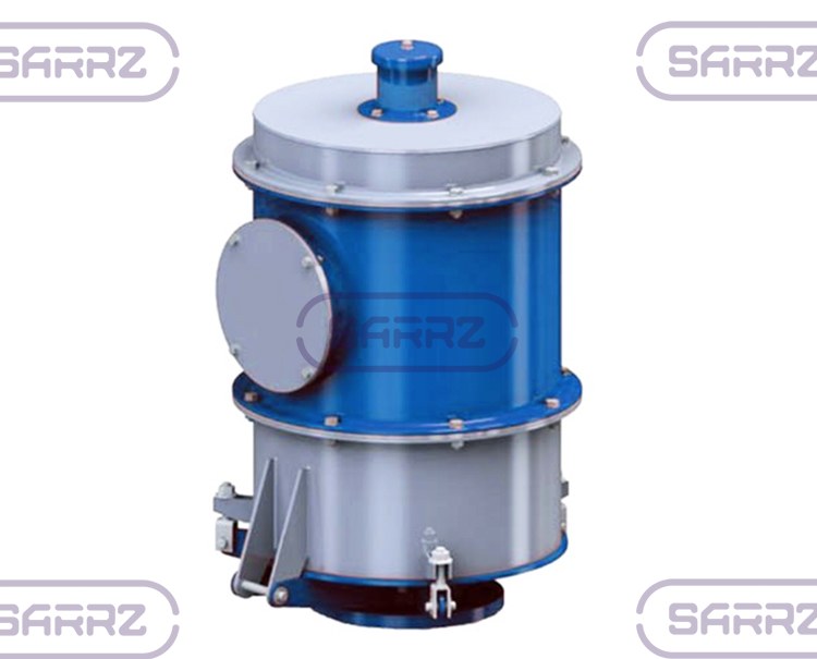
Product specification of impermeable breathing valve NDCM
NDKM valves are impermeable membrane breathing valves that are installed on the mount nozzle of vertical tanks operated up to 0.07 MPa. Their purpose is a timely connection of the gas space of the tank with the atmosphere in the process of filling/unloading processes or temperature fluctuations. This is necessary to prevent explosive situations resulting from changes in inner pressure. The design provides a fire safety, which protects the stored liquid from the flame in the gas space. Its mode of action is based on the movement of pressure and vacuum plates.
Impermeable breathing valves are manufactured in climatic categories N and placement category 1.
| NDKM valve drawing | Criteria | NDKM-100 | NDKM -150 | NDKM -200 | NDKM-250 |
|---|---|---|---|---|---|
 |
Diameter nominal of fitting, mm DT | 100 mm | 150 mm | 200 mm | 250 mm |
| Actuation pressure | 1372-1569 Pa | 1569-1667 Pa | |||
| Actuation vacuum | 157-196 Pa | 177-198 Pa | |||
| Throughput capacity, m3/h | 200 | 500 | 900 | 1500 | |
| Length L, mm | 300 | 510 | 510 | 610 | |
| Height Н, mm | 600 | 690 | 670 | 900 | |
| On center D1, mm | 170 | 225 | 280 | 335 | |
| Fixing hole diameter d | 18 mm | ||||
| Number of Fixing holes n, pcs | 8 | ||||
| Weight, kg, max | 25 | 50 | 55 | 77 | |
Design and function of breathing valves with a hydraulic gate KPG
They are used as safety valves and are installed together with mechanical breathing valves for additional protection. The principle of action is as follows: in case of pressure increase in the gas space (more than 0.02 kPa, or 5-10%) the latching liquid (oil) is expelled under the pressure, the hydraulic gate is closed and prevents the operating medium from flowing out the tank. In case of vacuum failure, the valve prevents atmospheric air from entering the tank.
It is recommended to install the hydraulic breathing valves in the horizontal orientation: the fluid in the valve may affect the operating value.
They are manufactured in climatic categories N, NF, TA, TH, placement category 1. For operation in cold climates, the moving valve rod and sealants are covered with a fluoroplastic coating that prevents from icing on the surfaces.
Specified service life of the KPG valves is 10 years. At the end of the period, it is required to replace the valve or to conduct preventive measures. For reliable operation, it is recommended to carry out a maintenance control of the oil condition and amount.
Technical specifications of relief hydraulic valves KPG
| Relief hydraulic valves KPG drawing | Criteria | KPG–100 | KPG–150 | KPG–200 | KPG–250 | KPG–350 |
|---|---|---|---|---|---|---|
 |
Diameter nominal of fitting, mm | 100 | 150 | 200 | 250 | 350 |
| Actuation pressure, Pa (mm w.g.), max | 1961 (200) | |||||
| Actuation vacuum, Pa (mm w.g.), max | 392 (40) | |||||
| Throughput capacity, m3/h, max | 200 | 500 | 900 | 1500 | 2700 | |
| Volume of sealing fluid (transformer fluid), l, max | 15 | 22 | 46,5 | |||
| Overall dimensions, mm, max: | ||||||
| length L | 980 | 980 | 1085 | 1180 | ||
| width В | 845 | 845 | 960 | 1030 | ||
| height H | 1278 | 1295 | 1370 | 1510 | ||
| Connection sizes, mm, max: | ||||||
| D | 205 | 260 | 315 | 370 | 485 | |
| D1 | 170 | 225 | 280 | 335 | 445 | |
| d | 18 | 18 | 18 | 18 | 22 | |
| n | 4 | 8 | 8 | 12 | 12 | |
| Weight, kg, max | 126 | 130 | 134 | 245 | 265 | |
Breathing valves design
The following parameters are taken into account for the correct operation of mechanical and hydraulic breathing valves:
- height above the tank
- pressure
- operating temperature
How to buy a breathing valve at our Plant?
The general quantities of the breathing valve is its throughput capacity and set pressure. To buy the tank's breathing valve, You can:
- call the Plant at +7(8452)250-288
- send an e-mail with operating requirements and operating conditions
- use the form "Request for quotation"
See also:
| Breather valves | Samplers | Tank hatches |
| Bottom cleanout boxes | Nozzles, nipples, connecting pipes, fittings | Flame arresters |
| Tank clap valves |