Flare units
Description
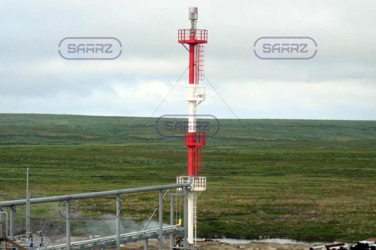
Flare units are systems that are used in oil and gas production and processing plants, oil refinery for smokeless combustion of gas emissions. Depending on the object, they can operate continuously, periodically or contingency.
As a result of many technological processes, waste gases are formed, which can not simply be discharged into the atmosphere due to the high content of environmentally harmful chemicals. To ensure that the recycling process is carried out safely, flare units are used, which fully combust the gases.
Functional operation of flare units
 From process units, vessels, apparatus or containers gas emissions through the supply pipeline first are fed to flare knockout drums and condensate drums, in which mechanical impurities, drip liquid and other suspended particles are removed. Then the stripped gas is fed to the flare stack, at the end of which there is a flare tip with flare burner, in which there is an ignite the flare.
For continuous ignition, it is recommended to install a pilot light with a supply of fuel gas and air pipelines. The total number of burners is calculated on the basis of the head radius, flow rate and volume, as well as the need to ensure flame resistance.
Types of flare units
The main types of flare units design and the principle of operation are:
- enclosed-flame flare, generally, are made horizontal or mobile (transportable on the chassis) and are applied in residential area, near inhabited objects and provide full absence of a flame, a smell, a smoke, noise, a thermal plume and radiation, allowing to use the formed energy in boilers or at heating of cold flare gas
- flare units of open type involves the direct movement of flare gas in the vertical flare stack of a length of over 4 m
Each type is designed according to an individual order based on the requirements and operating conditions. For example, a separator and a condensate drum can be equipped with a heater or thermal insulation to prevent condensate formation due to the low ambient temperature. This may also apply to the fuel gas supply pipelines to the flare pilot.
The design of the flare stack depends on the height and diameter and can be self-supporting or have guylines. For low- and high-pressure emissions, a double flare stack should be used to separate the flows.
| Flare unit | Flare tip |
Flare stack self-supported |
Flare stack with guylines |
Separator |
|---|---|---|---|---|
 |
 |
 |
 |
 |
Design of flare units
 The configuration* should ensure the completeness of combustion and explosion, fire and environmental safety:
- flare stack
- flare tip
- low and/or high pressure fuel and fuel gas supply pipelines
- primary flare burners and flare pilots
- solids separators for removing of mechanical impurities and liquid droplets
- pumps
- condensation drainage device
- steam supply devices for heavy gases
- sealers and cocks
- flame arrestors
- devices of flare ignition and keeping of a flame
- ignition devices (remote as well)
- sampling equipment
- control and measuring instruments for pressure and temperature data recording
- stairs and service platforms with fences
- alarm and fire extinguishing means
Flare unit scheme*
1-basement, 2-flare stack, 3-flare pilot, 4-flare tip, A-gas inlet, B-gaseous fuel inlet, C-gas condensate drainage, G-gas withdrawal

Technical specifications of flare units
| № | Criteria | Value |
|---|---|---|
| 1 | Operating ptoduct | natural, petroleum and other gas fuels |
| 2 | Product capacity, M. m3/day | 61-8000 |
| 3 | Pressure, MPa |
|
| 4 | Media temperature, ºС | from -30 to +300 |
| 5 | Burning point, ºС | up to 12000 |
| 6 | Flare stack hight, m | 7-120 |
| 7 | Flare stack diameter, mm | 100-1400 |
| 8 | Flare tip diameter, mm | 100-900 |
| 9 | The number of flare burners, pcs. | 1-5 |
| 10 | The number of flare pilots, pcs. | 1-3 |
| 11 | Service lifetime, years | 15-30 |
*the exact design and scheme depend on the developed project, operating conditions and should meet the requirements of the "Safety Guide of flare systems"
Manufacture and installation of flare systems
For the flare units manufacture various steel grades are used, taking into account their resistance to temperature increase during heating. In addition, the selection of steel takes into account the chemical composition of the combusted products: the material should withstand firing rate and chemical loads.
Wall thickness and mass are designed depending on the flare stack size, wind loads, seismic activity of the area and flow density.
The flare tip takes on the maximum temperature loads, so the pipelines are made of steel seamless pipes.
The exact design, geometric dimensions and configuration of the flare system are designed individually depending on the capacity (maximum and minimum per unit time), speed, pressure, density, temperature, chemical composition, working conditions, as well as in accordance with state regulations:
- GOST R 53681-2009 "Details of flare devices for general operations at oil refineries. General technical requirements"
- VNTP 3-85 "Technological design standards of oil, gas and water gathering, transport, conditioning for transport / storage facilities at oil fields facilities"
 |
 |
Advantages of flare systems of our own make
Their use will ensure:
- smokeless combustion of permanent or periodic gas emissions
- low gas flow density
- stable combustion without flame
- preventing air from entering through the top
- stable and complete combustion with automatic volume and pressure control
- compliance with environmental legislation
How to buy flare units of the Saratov Reservoir Plant manufacture?
The flare units are designed on the basis of operating conditions and Customer requirements. For your convenience, You can:
- call at +7(8452)250-288
- download the Questionnaire and send it by e-mail
- use the form "Request for quotation"
As a manufacturer, the Plant also provides other services for the construction of oil and gas facilities:
- design development of oil & gas facilities
- delivery of the manufactured equipment
- assembling and commissioning
See also: